The following languages are fully supported on our offering of international sites, including detailed product information and e-commerce funcitonality.
When selecting a hose for a specific application, it is common for the following to be considered: chemical compatibility along with pressure and temperature limitations. Often times, however, the physical fit of the hose can be overlooked with regard to the published minimum bend radius, a general lack of support or poor mounting orientation of the end connections. One way to ensure the hose will physically fit the application is to simulate the installation using 3D CAD software and verify all suggested installation principals are followed in the proposed layout.
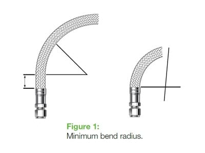
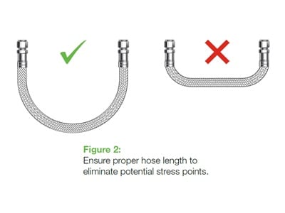
For any hose install, it is critical that a few principals are followed to allow for the longest life of the hose. Keep in mind that dynamic applications will require different considerations than a static application. One of the most important characteristics is to maintain a minimum bend radius to keep the hose under the least possible stress. This is commonly seen in applications where the hose is installed pointing up but allowed to have the free end hang horizontal in the opposite direction (Figure 1). This abrupt 180° change in direction is often more than enough to put the center line radius (or inside bend radius for certain hoses) less than the minimum suggested in the catalog. This radius issue could also be seen during install of a point-to-point application where the length of the hose has been improperly selected. This hose length, whether too short or too long, forces the hose to bend too sharply to meet the curve required (Figure 2).
A tight radius will only increase the stress within the hose and severely limit the overall expected life, but this is an easy fix! With just a few details and measurements, a model of the application can be generated in 3D space to show several possible routings that will follow the suggested bend radius.
The 3D CAD model is also integral in determining the correct hose length needed for those challenging applications. This will help reduce the possibility the hose could be bent past its suggested bend radius resulting in a reduction in the chance of fatigue failure.
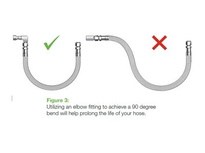
During this process, we may suggest alternative fitting combinations to help reduce any stress on the hose. For example, moving a 90° bend in the hose to a possible elbow fitting on an end connection (Figure 3) or moving from NPT ended hose to Swagelok tube adapter with a male connector to allow for an easier installation.
With this service you not only get a 3D CAD drawing package for the installation of the hose, but also a team at Swagelok Kansas City to help with the application and offer any suggestions to help make sure the hose is the absolute best for the job. Let us know if we can help you!
This document was prepared by Swagelok Kansas City | Little Rock | Omaha | Quad Cities. The information and recommendations are intended as general information only, are subject to change without notice, have not been verified by Swagelok Company, and do not contain or create any warranty or guarantee regarding accuracy or completeness. Users bear responsibility for determining the suitability of information, recommendations, and products for their own use and situations. Consult catalogs on www.swagelok.com for the most current information about Swagelok products and services.