Differential Instrumentation Impulse Lines: Ensure Accurate Readings Through Proper Installation

Ensure Accurate Readings Though Proper Installation
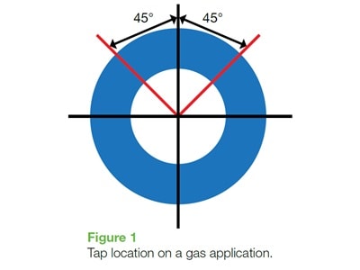
First, let’s consider a gas application. Imagine a line bisecting your process pipe vertically – that is running from 12:00 to 6:00. Ideal tap location is 45˚ on either side of this line at 12:00, with one tap on each side (Figure 1).
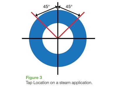
And finally steam measurements. Once more we are going to put the tapping points in the upper half of the pipe, 45˚ on either side of the 12:00 position (Figure 3).
Next let’s consider where we are going to mount the instrument. For our gas measurement we want to mount the instrument above the process pipe. This way any condensation which might occur will drain back into the process pipe, rather than accumulate in the impulse line. A good rule of thumb is to slope the lines 1:10 to help the condensation to drain and to avoid sharp bends or creating “traps” where condensation could build up. Provide tube supports if there is vibration. As a good practice, support ¼” through ½” tubing every three feet.
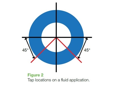
For steam measurements, while our tapping points are above the process pipe, we are going to mount our instrument below the process pipe. We want to mount two condensate pots or wells above the process pipe. Ideally these will be mounted at the exact same height, so that the impulse lines running from the condensate pots to the differential pressure transmitter have the same exact difference in elevation- this simplifies our calibration procedure. Impulse lines will run from the low point on the condensate pot to the high and low connections on our differential pressure transmitter. Once more a 1:10 slope is good to encourage trapped bubbles travel up to the condensate pots. The condensate pots are filled with water to the same level, as are the impulse lines running to the differential pressure transmitter.
Following these simple rules will help ensure the accuracy and repeatability of your transmitter readings.