Advanced Valve Porting: Simplify Your System Layout with Optimal Valve Selection

Simplify Your System Layout
with Optimal Valve Selection
It is the job of any fluid system designer or engineer to create systems that are functional, reliable, and maintainable. Often, as a system design grows in complexity, the need for additional instrumentation isolation and flow path selection also increases and if one is not careful can lead to poor system layout or redundant and complicated valving. This article discusses options available when evaluating instrumentation ball valves and covers examples where a system layout can be simplified to fewer valves and/or fittings by careful product selection.
Instrumentation ball valves are often used in chemical sampling, fluid injection, gas distribution and a host of other applications or systems across many industries. They are referred to as “instrumentation” (as opposed to “process”) valves because they are relatively small ranging from 1/16” to 1/2” pipe or tube connections and their relatively small size and often single-piece body construction lend them quite well to a variety of valve port designs and ball configurations. The valve design packages can range from two-port (or two-way) on/off valves to seven-port (or seven-way) switching valves with each having at least one option to alter the ball configuration to change its functionality.
Two-Way On/Off Valves
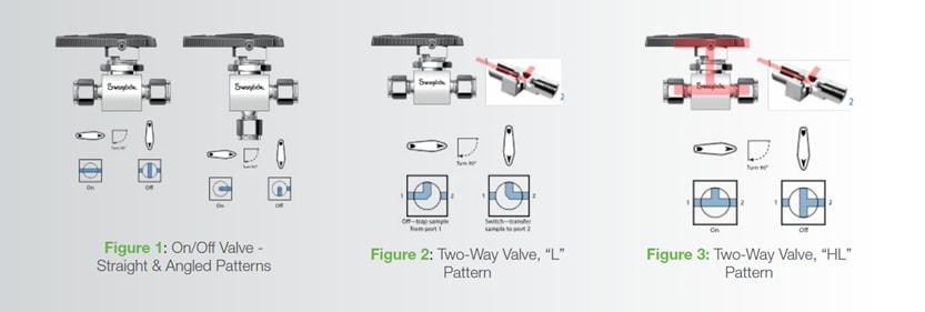
On-off or two-way valves are the simplest of the designs and require no real explanation as to their function. That said, there are still a few options and configurations to consider. The first is an option that might help to eliminate extra material and labor costs from the system by utilizing an angle patterned version (Figure 1) of the valve rather than using a tube bend or combination of fittings to facilitate the change in flow direction.
Two other options to consider are more related to the system function and the media used in the application. First, we introduce the “L” pattern ball configuration. As the name might suggest, the ball is drilled at 90° in the shape of an “L” as illustrated below in Figure 2.
Admittedly, when deployed in the two-way ball valve the “L” pattern ball is really limited to sample-injection type applications. The angle porting in the “L” pattern is designed to transfer the sample trapped within the ball cavity from Port 1 to Port 2.
A second alternate option in the on-off valve is the “HL” ball configuration. Like the “L” ball the “HL” gets its name from the port drilling and is illustrated in Figure 3.
From the illustration, one can see that the “HL” pattern ball is both drilled through from Ports 1 to 2 and at 90°. The “HL” port is particularly useful for inline on-off service in cases where the system media must not be trapped within the ball cavity when closed. Media entrapment between valves or within the ball cavity is important predominantly in applications where the thermal expansion of the process fluid may result in excessive pressure build up.
Three-Way Switching Valves
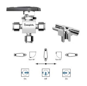
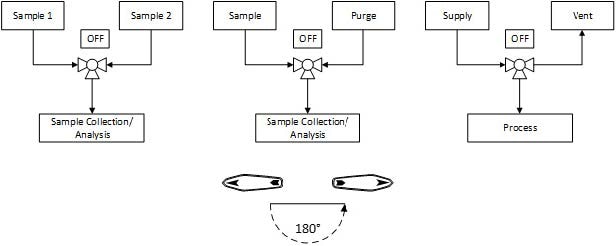
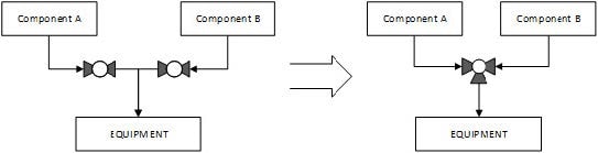
The three-way valve is a common replacement for two on-off valves arranged in parallel with a common pressure source. A common use for a three-way valve in sampling applications might be to either switch between samples or purging utilities to a sample collection or analytical device. The standard three-way valve design and port configuration can also be used as a process vent valve where in one position the valve is supplying the media to the process or equipment and in the other the valve facilitates the safe venting of that process or equipment.
In addition to the standard ball configuration, the three-way valve design can be configured with three other port arrangements: “L” Path, “H” Path and “HL” Path.
L-Path
The three-way valve with the “L” flow path offers a unique advantage over standard porting by reducing the required stroke of the valve to 90° rotation from 180°. The disadvantage to this is that there is no longer an ‘off’ position and that there is potential for cross-port flow during actuation.
In applications where a short valve stroke is desired, say an emergency vent valve, a system designer may utilize the “L” port in a three-way valve. The advantage to this is that the action is fast and simple to actuate the valve.
The “L” port can also be an attractive option if the system requires automation. While it is possible and somewhat common to outfit a valve with an actuator capable of 180° rotation; a more cost-effective solution is outfitting an “L” ported valve with an actuator capable of 90° rotation. This type of actuator is typically a more available option when considering fail-safe (or spring return) options. Another advantage of this solution is that in some cases the overall footprint of the valve, actuator, and accessories can be reduced allowing for an easier installation and eventual maintenance.
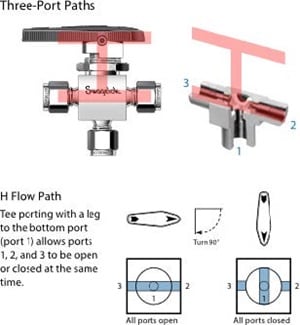
H-Path
“HL” Path
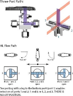 A variant of the “H” ported flow path is the “HL” flow path. The “HL” ball is drilled at 90° and provides for continuous flow from Port 1 in all three valve handle positions. The main difference between the 3-Way “HL” and “H” port is that this valve configuration allows for both stream selection and mixing but removes the shut-off function.
Summary
In summary, the type and number of ball valves used in a fluid system are entirely up to the requirements of the application and the system designer. The purpose of this article was to share some information regarding the numerous options available when designing a fluid system and often these options can simplify the system layout and improve reliability.